Debugging the Cremenco TU-ART Card
This is the first [and potentially the last :( ] time I am writing for this blog. I’ve been working at the VIP for 2 semesters, and my work primarily focused on getting the IMSAI 8080 to work. Here I document my work with the Cremenco TU-ART card, and how Calvin and I tried to get it to work with a PuTTY terminal.
Background
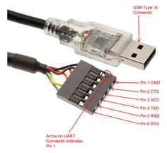
Work done previously by Calvin had led to the discovery of the FTDI interface, a way to convert USB communication to Serial communication (TTL level) and vice versa.
This greatly simplifies things for us, since we now have a way to plug in the Cremenco card straight into our laptop and using PuTTY, display the Serial output that CP/M will eventually display its output to and take keyboard input from.
Breakdown of Cremenco TU-ART Card
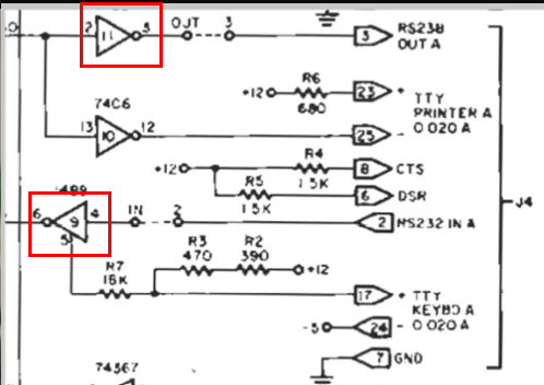
- 2 Parallel IO and 2 Serial IO ports. Serial IO are RS232C compatible
- Interrupt Capabilities: On board Priority Encoding, interrupt generation, interrupt acknowledgement, and daisy chaining expandability
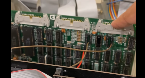
Note the wires coming out of the board’s IC Sockets, and not out of the Jumper Header. FTDI works at 5V TTL levels, and these are the levels before it goes into the ICs [which are basically buffers] before being stepped up to 12V levels of the RS 232C standard. We removedd the ICs that were converting the TTL to RS232, and connected the right pins to our FTDI cable.
Previous Iteration of FTDI Connection (+ mistakes)
Connection 1:
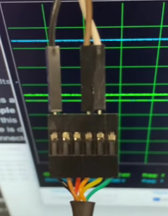
Connection was made to Rx and Tx only. Rx of IMSAI was connected to Tx of FTDI. Tx of IMSAI was connected to Rx of FTDI.
Feedback:
This Connection was a mistake because
-
No GND connection was made.
-
Rx and Tx were inverted. While a regular UART connection does require this inversion, the FTDI did this internally for us.
Connection 2:
Connection was made to Rx and Tx and GND. Rx of IMSAI was connected to Tx of FTDI. Tx of IMSAI was connected to Tx of FTDI.
Feedback:
- This is the connection being used currently. While the connection does not work the way we expect it to, we are working on debugging this one.
Change in connection output
The first issue noticed on Connection 1 was that there were visible signals rather than noise on the Oscilloscope output.
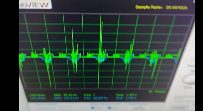
There was a 60 Hz Disturbance on both lines, which eventually turned out to be caused by the transformer over which the wire was running. Since all 3 wires were near the transformer, the disturbance would affect all 3 relatively the same way, and therefore would cancel out since the ground picked up the same noise all the other wires were picking up.
However, one thing that was noticed was that the oscilloscope was interfering with the Serial communication between the 2 devices, and so had to be removed to continue.
There were inconsistencies with the voltage levels (typically, they are driven to 5V, but here they seemed to be driven to just 230 mV, which I felt was the next issue we should look at debugging).
Driver Code for the TU-ART
The reason why the TTL logic signals were not correct was because the card had not been reset after the IMSAI boots up, and hence it was not driving any signal on the output wires. We pulled up some of the example code from the TU-ART documentation and began using that as a reference to write some driver code to reset the TU-ART and try and write bytes to a PuTTY shell on our laptop.
Driver Code Iteration 1 - Simple Write
Using Appendix A as a starting point, an attempt was made to transmit data to a PuTTY terminal. The terminal did not receive any data, and ghost bytes [0x00 or null] were logged by PuTTY on every program reset while the program was running. This was not the desired output.
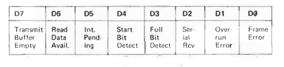
The program pointed out an issue: The device had its TBE bit set to 0 when the status register was read. This meant that the device was not ready to read, even though we had just reset it, which would case that bit to be set high.
The Program was modified by me to the one in Appendix B. This program was then run. Upon user intervention, it was noticed that:
-
TBE is still not set – the device is still not ready to transfer data!
-
RDA is set – The device wants us to read data instead!
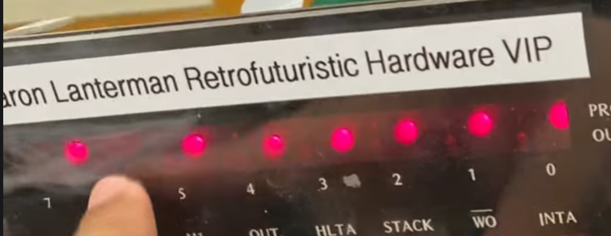
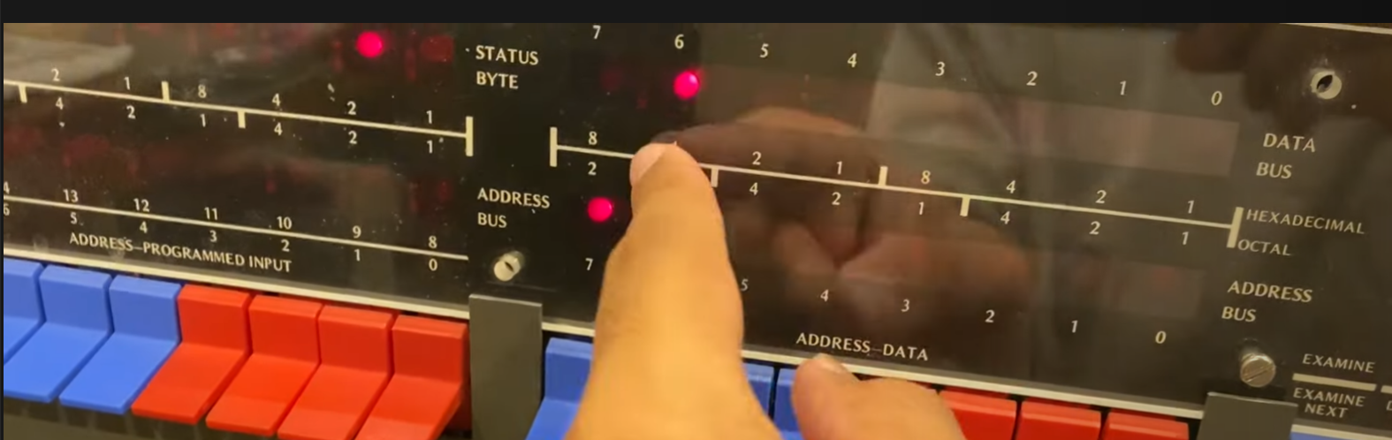
Note that the Front Panel Display byte (updated through a OUT 0xFF) shows the bits inverted. This was because it was easier to have those LEDs pulled down when HIGH. However this is only applicable for the OUT 0xFF LED display. All other LED displays on the front panel [the data and address buses] show the bits as they are.
Driver Code Iteration 2 - Greedy Read
We handled this by letting the user intervene, allow the program to read some data, and then continue. Code in Appendix B shows the modified assembly.
On my first try after this intervention was added, the device read the initial byte, and then the TBE bit was set to 1! This showed the data we were outputting on the IMSAI front panel, 0x88. However, there was still no transmission seen on the PuTTY terminal. Unfortunately, this was not reproducible. This happened only 3 times after, before it just stopped setting TBE status bit high. There was no change made to hardware, we were just uploading software to the device and restarting.
Driver Code Iteration 3 - RDA Debugger
Finally, I decided to try and see what the data the TU-ART was asking us to read. Was the card trying to give us some initial data? Was there some data transmitted by my laptop that I had to process? I updated the code to automatically display all RDA bytes it reads, and have the user verify each byte.
When this program was run, the exact same byte was read: 0x40. This also corresponds to a status byte indicating an RDA. This was confusing. Initially, I thought the display was not updating properly after the status byte had been displayed, but this was soon disproved by checking the IMSAI front panel using single step instead of run to run programs.
The thing is, when single stepping a program on the front panel, if you encounter an IN or OUT instruction, the IMSAI will actually show you the byte being read into or from the accumulator (A) register.
This meant that when I ran the IN instruction to read a received byte from the TU-ART, it was indeed returning 0x40 to the IMSAI.
At this point, I reached the conclusion that the TU-ART board is not working as it should. I would most likely attribute this to a hardware defect, maybe an IC on the board had been burned out? We can rule out faulty connections on the board, since I had continuity checked all the different components, and even checked resistances and capacitances.
The device does reset successfully. It was able to drive the Serial connection lines to around 4.5V, which is the desired behaviour. The perpetual 0x40 byte, that does not reset the RDA status bit is indicates that there is something on the board not working as expected.
Conclusion
The conclusion was reached that we need to try and use a different UART board on the IMSAI, and Professor Lanterman just pinged us a couple hours ago that the new ones he had ordered have arrived! Hopefully one of those has better success!
Appendix
Appendix A [Simple Prorgam to I/O via Serial Port A on Cremenco TU-ART board – original]
; Adapated from Programming Examples in:
; http://www.s100computers.com/Hardware%20Manuals/Cromemco/Cromemco%20TU-ART%20Manual.pdf
; Calvin Khiddee-Wu
; 4/10/22

ABASE: equ 080H

BAUDA: equ 0C0H
ABDR:  equ ABASE+3 ; Baud rate port A

RESET: equ 9 ; RESET + INTA Command
ACMD:  equ ABASE+2

MASKA: equ 0       ; No interrupts from A
AMSK:  equ ABASE+3 ; Interrupt mask port A

ASTAT: equ ABASE+0
ADATA: equ ABASE+1
TBE:   equ 80H	   ; Buffer empty bit

; Echo program
org 0000H
; Initialization
	mvi a, RESET
	out ACMD    ; Device A reset

	mvi a, MASKA
	out AMSK

	mvi a, BAUDA
	out ABDR

; Send character output
outchar:
	in ASTAT
	ani TBE
	jz outchar
	in 0xFF
	out ADATA
	jp outchar
Appendix B [Simple Prorgam to I/O via Serial Port A on Cremenco TU-ART board - modified]
; Adapated from Programming Examples in:
; http://www.s100computers.com/Hardware%20Manuals/Cromemco/Cromemco%20TU-ART%20Manual.pdf
; and from a similar program authored by Calvin Khiddee-Wu
; Ananay Gupta
; 4/11/22

ABASE: equ 080H

BAUDA: equ 0C0H
ABDR:  equ ABASE+3 ; Baud rate port A

RESET: equ 9 ; RESET + INTA Command
ACMD:  equ ABASE+2

MASKA: equ 0       ; No interrupts from A
AMSK:  equ ABASE+3 ; Interrupt mask port A

ASTAT: equ ABASE+0
ADATA: equ ABASE+1
TBE:   equ 80H	   ; Buffer empty bit
RDA:   equ 40H     ; Read Data available

; Echo program
org 0000H
; Initialization
	ld a, RESET
	out ACMD, a    ; Device A reset

	ld a, MASKA
	out AMSK, a

	ld a, BAUDA
	out ABDR, a

; Send character output
outchar:
	in a, ASTAT
	and TBE
        cp TBE        ; check for a TBE, if one exits, wait for user to intervene
        jp z, END

        in a, ASTAT
        and RDA       ; check if data is available to be read. if there is, wait for user to intervene
        jp z, END

	ld a, 88H       ; we want to transmit 0x88
        out 0FFH, a   ; sanity check: display to front panel LEDs
	out ADATA, a    ; output as data from Serial output A
	jp outchar      ; loop

END:
in a, ADATA
out 0FFH, a
in a, 0f0h
cp 0F0H
jp z, outchar
jp end
Appendix C [Program to Read/Write bytes and manually control bytes via Serial Port A on Cremenco TU-ART]
ABASE: equ 080H

BAUDA: equ 0C0H
ABDR:  equ ABASE+3 ; Baud rate port A

RESET: equ 9 ; RESET + INTA Command
ACMD:  equ ABASE+2

MASKA: equ 0       ; No interrupts from A
AMSK:  equ ABASE+3 ; Interrupt mask port A

ASTAT: equ ABASE+0
ADATA: equ ABASE+1
TBE:   equ 80H	   ; Buffer empty bit
RDA:   equ 40H     ; Read Data available

DISP: equ 0FFH
STACK: equ 200H

; Echo program
org 0000H
; Initialization
    ld a, 0
    out 0xFF, a
    ld SP, STACK
	ld a, RESET
	out ACMD, a    ; Device A reset

	ld a, MASKA
	out AMSK, a

	ld a, BAUDA
	out ABDR, a

	ld b, 0

START: ; outputs status byte and waits for user to confirm that they have seen it
in a, ASTAT
out DISP, a
call INPLOOP
jp READ ; read next received byte

READ: ; outputs byte read from TU-ART and waits for user to confirm that they have seen it
in a, ADATA
out DISP, a
call INPLOOP
jp START ; read status byte

INPLOOP: ; waits for user to complain that they have seen the byte that is on the display and returns
in a, DISP
cp b
jp z, RETURN
jp INPLOOP
RETURN:
inc b
ret