New SIO Compatable Serial Card
Although the system we have does include an original IMSAI SIO-2 card, which includes 2 RS-232 compatable serial interface. However, we are unable to get the card working reliably. (#TODO Link Post Here) While repairing the original IMSAI SIO-2 card is still in the long term plan, we decided to implement a custom and modern serial solution that emulates the IMSAI SIO-2 board with Intel 8051 USART communication interface IC.
Overall Planning
The overall plan is to use the USART capability of the STM32F103C8T6 MCU to recieve data on the output port of the S100 Bus. However, due to the lack of pins on the MCU, and the level shifting required between the RS-232 interface and the TTL-UART interface of the MCU, there are quite some supporting circuitry required for this to function properly.
Circuit Design
RS-232 to TTL UART Level Shifter
I think it would be a good idea to describe the problem first before I go on to talk about solution. It would be coufusing wouldn’t it be? So in short, the RS-232 standard defined the logic level of the serial interface using both positive and negative voltages. A logical ‘1’ is defined as any voltage between -3V and -18V, and a logical ‘0’ is defined as voltage between +3V and +18V. The exact voltage of operation may differ depending on the reciving and sending device. The voltage is not as big of the problem, as through testing, we discovered that most modern serial interface will happly accept ~0V as a ‘1’, and positive voltage as a ‘0’. However, the key problem comes in when we look at the specification of the TTL serial interface. Where a logical ‘1’ is defined as VCC (Commonly 5 or 3.3V), and a logical ‘0’ is defined as ~0V. An easy solution would be use an IC like MAX232 from Maxium Integrated. However, purchasing IC takes time and it’s always better to use commonly found component from both economic and maintainability perspectives.
//TODO Insert Circuit Diagram of the RS-232 Level Shifter
The above circuit is what we decided to use for the RS-232 level shifting. It consists of one pair of NPN and PNP transistor (2N3904 and 2N3906). Essentially used a charge-pump to provide the negative voltage required by the RS-232 standard.
3.3V to TTL Logic Level Shifter
The IMSAI operated at TTL Logic level. Although many pins on the STM32 are 5V tolerant(It can acceot 5V voltage level), non of its pin can produce a high enough voltage for the IMSAI to consider it a logical ‘1’. Thus we need a PNP transistor with 2 supporting resistor on each of the DI* lines to do level shifting.
Measurement
In order to operate on the OUTPUT port of the Intel 8080 processor, we need to decode the signal on the S100 Bus. Due the failure of me last time naively trying to construct a output address decoder, I will make some measurements before continuing.
OUTput port signal decoding
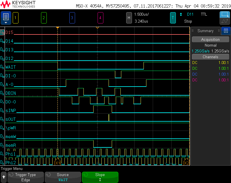
The above image is the Intel 8080 processor executing and OUT instruction to port 0xFF (The Lights) with data 0xFF.
Exact instruction listing.
```asm CMA ; Complement A, as A is initialized to 0, this makes it 0xFF OUT 0xFF ; HLT ; HALT is added to assure clean signal capature. The Wait line is used for trigger ```As we can see from the logic anaylizer, the address of the port is first written to the S100 Bus, then sOUT signal comes HIGH, at this point the address on the bus should be a valid OUT PORT address. (This address is duplicated (A0-A7 = A8-A15) on the bus). This is when port matching could happen; however, data is not valid at this moment. Output data is only valid when sOUT is HIGH AND P̅W̅R̅ is LOW.
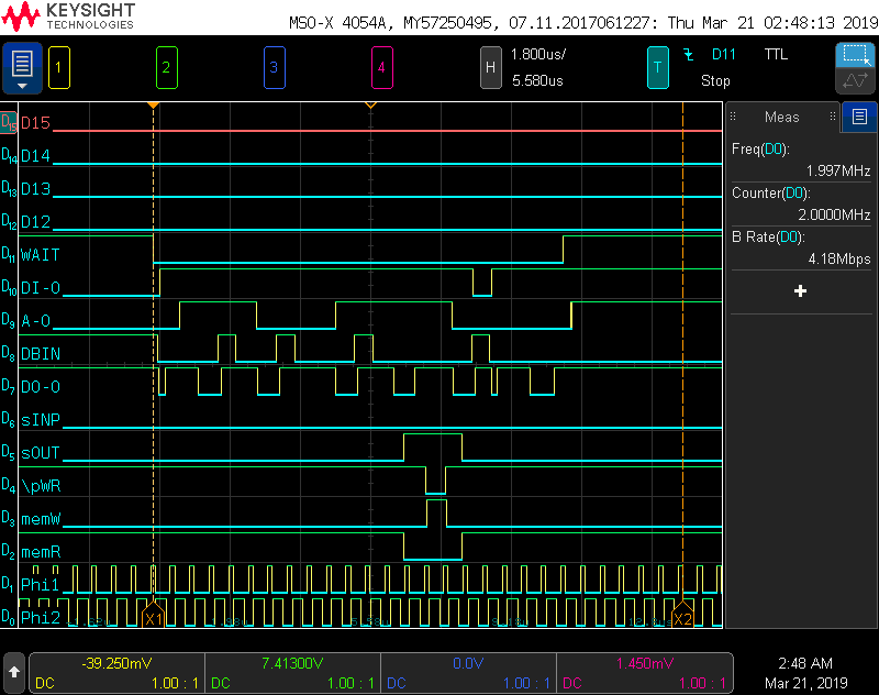
Input Port Signal Decoding