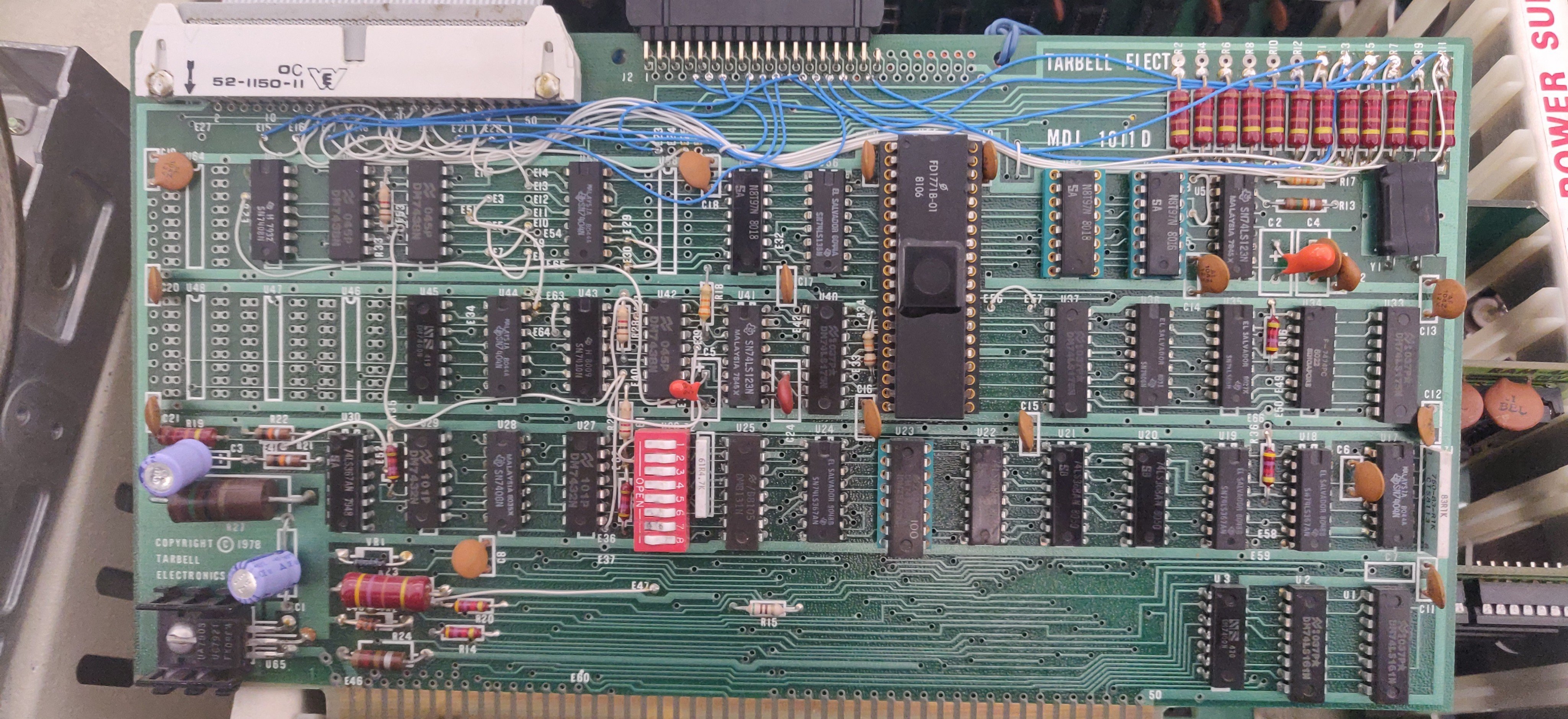
Tarbell MD1101 SSSD Floppy Controller
MD1101
Our machine came with a Tarbell MD1101 Single Side Single Density (SSSD) floppy drive controller along with 2 8" floppy drives.
The Tarbell Floppy Disk Interface was a programmed-data-transfer (not DMA) device utilizing Port I/O, similar for example to the SD Systems Versafloppy boards. It was designed to work with a variety of standard-size floppy disk drives. It includes a 32-byte ROM bootstrap program, which was automatically enabled when the computer RESET button was pushed, and which switched itself out after the bootstrap had run. In this way, no part of the computer 64K of memory needed to be dedicated to Read-Only-Memory (ROM).
The interface ran at the standard speed of 250,000 bits per second, and the normal formatted capacity per diskette of 256 kilobytes. Places for two connectors were provided on the board.
Documentation Typo
The WD1771 chip used by the card actually does not support multi-drive configuration. The card used a 74LS175 Quad D Flip-Flop to select between up to four drives. Drive select only use 2 of the 4 bits in the flip-flop, the other 2 seems to be releatively undocumented. However, the provided sample code for selecting drive would not work. It would cause any subsquent input from the controller to hang the CPU. (Stuck in IN DWAIT)
After a lot of trail and error along with reading the tiny text schematics, we are able to narrow the problem downto that the code is incorrectly setting one of the bit on the Flip Flop. Effectively disabling the controller interrupt request handling thus causing it to hang forever.
Modified Code Listing
SELECT_DIRVE:
;Select drive in register C
MOV A, C ; Move drive number to A
CMA
ANI 3 ;Limit drive selection to only 0-3
RAL! RAL! RAL! RAL ;shift left by 4
ORI 0x82 ;MODIFIED: original is 0x2
OUT DEXT
RET ;return from subroutine
---
5.25" Drive Mod
In addition to the 8" drives, we also happen to have a few 5.25" drive on hand. that we would like to operate as well. Upon close inspection, the 5.25" and 8" (Shugart 801) interface are not very different from eachother. The only difference being the 5.25" drives has a Motor Enable line in lieu of a Head Load (This is due the the difference in physical construction of the drive.) But I think it is okay to subsitute the signal. Since if achieve the same effect which is to begin reading the diskett. Conviently the board has a free 40 pin mounting hole for a additional 2 8" drive. We decided to use this connector for our 5.25" drive header. This required a lot of jumper wires (All the blue mod wires below).
Drive Pin Mapping
The pads are labeled across the MD1101 board and are listed with their corresponding name here. They must be wired to the corresponding “Mapped To” pins on the 5.25" floppy drive.
| Pad | Name | Mapped To |
|---|---|---|
| E23 | DS0* | 16 (motor en. B) |
| R3 | INDX0* | 8 (index) |
| R1 | RDY0* | 34 (ready) |
| E19 | HLD0* | |
| E20 | HLD1* | |
| E17 | HLD2* | 12 (drive sel. B) |
| E25 | HLD3* | |
| E22 | SO* | 18 (direction) |
| E21 | SI* | 20 (step) |
| E15 | WD* | 22 |
| E16 | WG* | 24 |
| R7 | TR00* | 26 (sense track zero) |
| R5 | WRPT0* | 28 |
| R11 | RDAT0* | 30 |
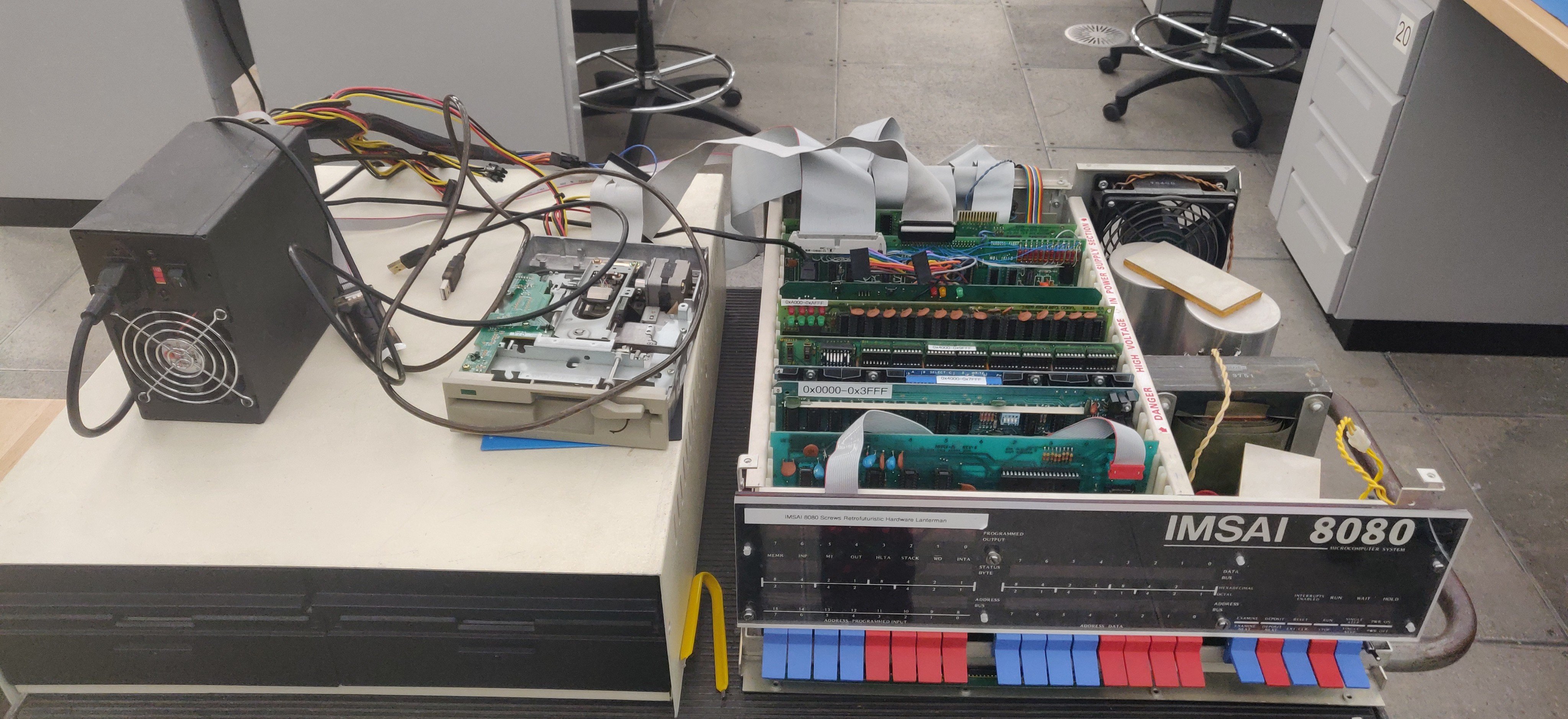
Pictures